You can access layers and layer information in the Contents window. The Contents window appears when you click Contents on the toolbar. This window contains three panes:
- Layers—Lists all the layers in a scenario
- Legend—Displays the associated symbols for each layer
- Jobs—Displays the status of the jobs created by the analysis tools
This topic describes layer-related functionality available in the Layers pane.
Layers pane
The Layers pane has five sections: Active Scenario, Study Areas, Data Layers, 3D Layers, and Basemap.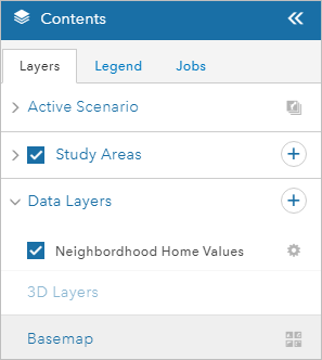
The Active Scenario section contains the active scenario layers for your project. Active scenario layers are the layers in which you can sketch, paint, and split features. Each GeoPlanner project has one or more active scenario layers that are defined in a template. You can add new layers to an existing set of active scenario layers in a project using the Add to Design Layers tool.
The Study Areas section contains study areas in your scenario. Study areas are used to define an area of interest for analysis.
The Data Layers section contains layers that are used for visualization and analysis. Some layers can also be used in the dashboard. You add layers using the Add Data tool on the Explore tab.
Basemap displays the name of the active basemap. You can change the basemap by clicking the Change Basemap button.
To access the context menu, click the Options button  next to a layer in the Layers pane.
The menu lists layer-related functionality in GeoPlanner, including the following:
- Zoom to—Sets the map extent to the extent of the selected layer
- Transparency—Sets the transparency level of the selected layer
- Visible Range—Specifies the zoom levels that content are drawn at in a layer
Tip:
When a layer is out of range, its name appears in a lighter gray color in the contents and legend than the layers that are in the visible range.
- Move up—Moves the selected layer one level up in the table of contents and the map.
- Move down—Moves the selected layer one level down in the table of contents and the map.
- Table—Displays a tabular view of the information about features in a layer.
You can view the attributes of a layer in a table. Click the Options button
 to adjust the table in the following ways:
- Default sort order—Reverts the sort order to the default.
- Clear the current selection—Current selections are cleaerd.
- Show/Hide columns—Opens a list containing the column headers in the table with check boxes that you can check to make a column appear in the table, or uncheck to hide the column in the table.
Note:
Tables are only available with feature layers.
- Layer Symbology—Opens a modal with a preview of the symbology for the data layer. You can specify a shape and size for the layer's symbol or upload an image to use. You can also choose the symbol fill color, outline color, and set its transparency. This is only available for data layers.
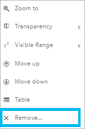
- Remove—Removes a layer from the table of contents and the map.
- Classify—Creates an assessment or suitability layer by reclassifying data into a zero-through-nine scale based on attributes. You can use this layer as an assessment layer in the secondary chart of the dashboard.
- Rerun Analysis—Opens the tool that was used to create the layer and repopulates all of the parameters.
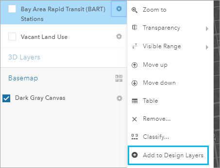
- Add to Design Layers—Adds the layer to the Active Scenario group so you can sketch and paint using the design types defined in that active scenario layer. This option is only available for feature layers.
- Properties—Opens the Layer Properties window for the selected layer.
- Export Model—Allows you to export the results of your weighted raster overlay model as a layer to your organization or download raster data from GeoPlanner as a .tiff file for use in ArcGIS Desktop. This is only available for raster data.
Note:
- For best results, view the downloaded .tiff file in ArcGIS Pro.
- The option to export a new image layer to your organization requires a valid license for ArcGIS Image for ArcGIS Online.
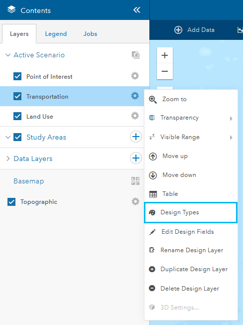
- Design Types—Opens a modal showing all design types for the chosen active scenario layer. You can edit and change your active scenario layer's design types from this modal. This is only available for active scenario layers.
- Edit Design Fields—Opens a modal showing all fields associated with the chosen active scenario layer. You can change field aliases, delete fields, and add new fields from this modal. This is only available for active scenario layers.
- Rename Design Layer—Changes the name of a chosen active scenario layer. This is only available for active scenario layers.
- Duplicate Design Layer—Creates a duplicate copy of an active scenario layer. This is only available for active scenario layers.
- Delete Design Layer—Deletes a chosen active scenario layer from your project. This is only available for active scenario layers.
The following sections detail how you can use some of these functions.
Remove a layer from a project
GeoPlanner allows you to remove certain types of layers from the map. You cannot delete basemap layers from your project, but you can remove other layer types. These layer types include scenario layers, analysis results, operational layers, weighted overlay model layers, and other layers added directly from your ArcGIS organization. Use the following process to remove a layer from your project:
- Click the Contents button to open the Contents window.
- In the Layers pane, click the Options button
 next to a layer name and click Remove.
Change the order of layers in a map
You can set the order of active scenario layers, 3D layers, and data layers in the Contents pane. You can only move layers in their section of the Contents pane. For example, you cannot move an active scenario layer outside of its section so that it appears below a data layer.
- Click Contents.
- In the Layers tab, click the Options button
 next to the layer name and click Move up or Move down.
 Depending on the layer type and the order of the layer in the Contents pane, the Move up or Move down function can be hidden or unavailable. For example, these two functions are not available for basemap layers.
Tip:
You can drag layers in the Contents pane to reorder them on the map.
Add to design layers
Each GeoPlanner project is created from a template. Templates are part of a group in an organization, and include a web map and a hosted feature service which contain one or more feature layers.
You may find that the types and default values are not applicable for your planning domain and project. GeoPlanner allows you to append your own layers as active scenario layers. This can help you plan and sketch using the symbols and types that are specific to your planning domain. The following steps describe how to add an existing layer as a new active scenario layer:
- Add a layer to GeoPlanner.
For the layer to be useful in GeoPlanner as an active scenario layer, it must have types. If it does not have types, it must have a unique value renderer.
- Click the Options button
 next to the data layer in the Contents pane and click Add to Design Layers.
- On the Add to Design Layers dialog box, type a new name for your active scenario layer in the New Name text box.
- Optionally, check Import features to import both schema and data into your new design layer.
- Click Import.
The Add to Design Layers dialog box closes and the project reinitializes. When reinitialization completes, a new active scenario layer appears in the Active Scenario group.
Change design layer symbols, type labels, and default values
Layers have types. Types can represent different entities such as land use or zoning. You can change the symbols, labels, and default values of types in an active scenario layer.
- Click the Options button
 next to an active scenario layer in the Active Scenario area of the Contents pane, and click Design Types.
- On the design type editor, click a type in the list and perform one of the following actions:
- Click the Symbol tab to make changes to a symbol's color and outline.
- Click the Type tab to change a type's label.
- Click the Default Values tab to change a type's default values.
Note:
You can add a new design type to a layer or delete an existing type by clicking the Add or Delete button .
. - Click Save to save your changes and reinitialize your project.
Define a study area
In a GeoPlanner project, a study area defines a planning subarea. A planning subarea can represent a neighborhood, habitat, or any other location type. Once you enable a study area, GeoPlanner focuses its indicators, import operations, and visual review on that area. An active study area displays a mask that obscures everything outside the study area. The dashboard only reports on features that intersect or lie inside of an activated study area. The Import Scenario tool only imports features that intersect or lie inside of an active study area.
Follow these steps to define a study area:
- Click the Contents button
 to open the Contents pane.
 - Click the Layers tab, hover over the add button, and click Add Study Area.
- On the New Study Area dialog box, click Draw an area on the map.
- Click Polygon and draw one or more polygons on the map to define your study area.
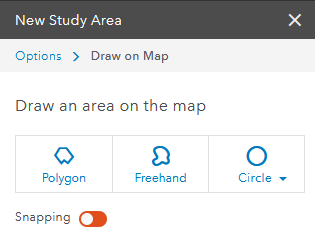
- Type a name for your study area and click Save.
Tip:
You can also create a study area from an existing feature by clicking the Import link in a pop-up window.
Edit design fields on a design layer
You can add, delete, and rename design fields for a chosen design layer.
Complete the following steps to add a new field to a design layer from your project.
- Open the Contents pane.
- Click the Options button
 next to an active scenario layer in the Active Scenario area of the Contents pane, and click Edit Design Fields.
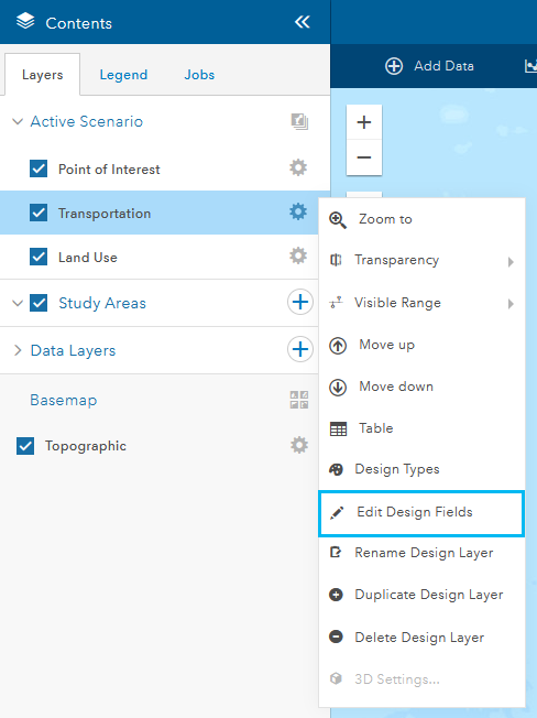
A modal containing the design fields for your chosen layer appears.
- Click Add Field to add a row to the table of design fields.
- Type a name in the text box in the Field Name column.
- Type a name in the text box in the Display Name column for the field.
- Choose a data type from the drop-down menu in the Type column.
- Optionally, click the Remove button
 next to the field you added to discard your changes.
Tip:
You can click the Delete Field button
 next to existing rows you want to delete from the table.
 - Click Save.
The changes you made to your design fields are saved to your project.
Change data layer symbology
You can change the color of the fill and outline of a data layer symbol, as well as its transparency.
- Open the Contents pane and browse to the Data Layers area.
- Click the Data Layers drop-down arrow if the list of data layers aren't visible.
- Click the Options button
 next to the data layer you want to modify.
Additional options for the data layer appear.
- Click on Layer Symbology and adjust the symbology as needed.
You can update the symbology in the following ways:
- Change the symbol icon and its size, or upload your own image with the Shape tab active.
- Change your symbol's fill color in the Fill tab and the outline color in the Outline tab, and adjust the transparency of your symbol.
- Change the color of a line data layer, adjust the transparency, line width, choose a pattern, or make it an arrow.
Note:
The tabs that are available depend on whether your data layer is a point, line, or polygon. - Click Save to save your changes and return to your project.